The Complete Lifecycle Of An Oil & Gas Project: Application of Design Engineering Softwares PART 4
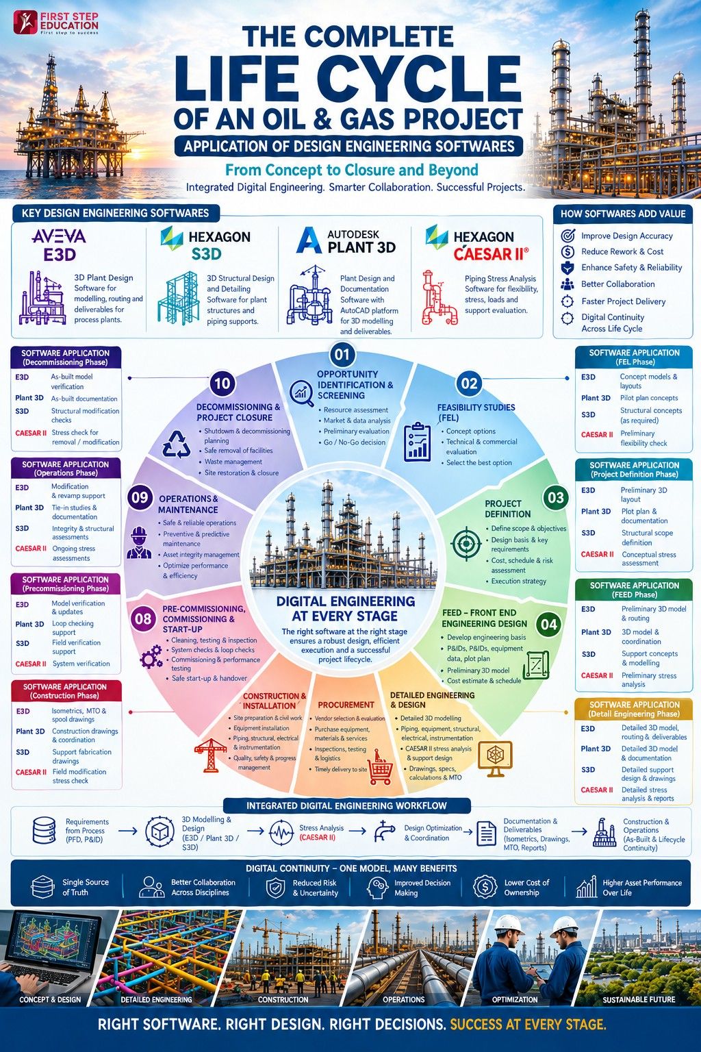
The main applications of design engineering softwares starts during FEED and becomes much more intensive during Detailed Engineering, but some of these tools can be used earlier for concept development and later for construction/operation support. Here we considered some softwares which are of highly usage all over the world. Ie, E3D, S3D, Plant3D & CAESAR II.
1. Where E3D, SP3D and Plant 3D are actually used
These are primarily 3D plant design/modeling platforms.
They are heavily used from FEED → Detailed Engineering → Construction.
During FEED
The 3D model starts becoming useful for:
- Preliminary equipment arrangement
- Plot plan development
- Equipment positioning
- Preliminary pipe routing
- Pipe rack arrangement
- Access and maintenance studies
- Clash/interference checking
- Preliminary quantity estimation
- Constructability reviews
At this stage, the model may not have the same level of detail as the final construction model.
For example:
Process Engineer → PFD/P&ID
↓
Equipment Engineer → Equipment data
↓
Piping Engineer → Equipment arrangement
↓
3D Designer → Preliminary model
↓
Engineering Team → Layout review
This allows the team to identify problems while changes are still relatively inexpensive.
2. Detailed Engineering – This is where 3D design software becomes critical
This is the core working phase for E3D, SP3D and Plant 3D.
The model is developed in much greater detail.
Typical activities include:
Equipment modelling
- Vessels
- Pumps
- Compressors
- Heat exchangers
- Tanks
- Package equipment
Piping modelling
- Pipe routing
- Valves
- Flanges
- Fittings
- Specialty items
- Reducers
- Supports
- Instruments
Layout development
Engineers consider:
- Pipe rack dimensions
- Equipment spacing
- Maintenance access
- Operator access
- Escape routes
- Crane access
- Valve accessibility
- Equipment removal routes
Clash detection
The 3D model allows designers to identify conflicts such as:
Pipe vs Pipe
Pipe vs Structure
Pipe vs Equipment
Pipe vs Cable Tray
Pipe vs HVAC
Pipe vs Instrument
before construction.
This is one of the major advantages of 3D plant design software.
3. Where CAESAR II fits
CAESAR II is different from E3D, SP3D and Plant 3D.
The 3D plant design tools answer:
"Where should the pipe physically go?"
CAESAR II primarily answers:
"Can the piping system safely withstand the loads and movements associated with its operating conditions?"
For example, consider a hot process line.
The line may be at:
350°C
When the line heats up, it expands.
The piping system therefore experiences:
- Thermal expansion
- Weight loads
- Pressure loads
- Occasional loads
- Wind loads
- Seismic loads
- Equipment nozzle loads
- Support reactions
CAESAR II is used to evaluate these effects.
4. CAESAR II during FEED
During FEED, CAESAR II may be used for preliminary flexibility and stress assessments, especially for critical piping systems.
Examples include:
- High-temperature piping
- Large-diameter piping
- Long pipe runs
- Critical equipment connections
- Steam systems
- Compressor piping
- Pump piping
- Large process lines
The objective is not necessarily to perform every final stress calculation.
Instead, engineers want to answer questions such as:
Is the proposed piping arrangement flexible enough?
Will thermal expansion create excessive loads?
Will equipment nozzle loads be acceptable?
Do we need expansion loops?
Where should major supports be located?
This information can then influence the 3D layout.
5. The important connection between 3D software and CAESAR II
This is where the workflow becomes particularly interesting.
A simplified workflow is:
P&ID
↓
Equipment Arrangement
↓
3D Piping Model – E3D / SP3D / Plant 3D
↓
Piping Routing
↓
Pipe Supports
↓
Stress Model
↓
CAESAR II
↓
Stress Results
↓
Modify Piping Layout / Supports
↓
Update 3D Model
This can become an iterative engineering process.
For example:
The 3D designer routes a hot pipe from Equipment A to Equipment B.
The stress engineer analyzes it in CAESAR II.
The analysis shows excessive thermal expansion or equipment nozzle loading.
The piping arrangement may then need to be changed.
The designer might:
- Add an expansion loop
- Change routing
- Move a support
- Change support type
- Increase flexibility
- Modify anchor locations
The revised arrangement is then re-analyzed.
This cycle continues until the piping system satisfies the applicable design requirements.
6. Construction Phase – 3D software becomes useful again
After the design is finalized, the 3D model becomes an important construction reference.
It can be used to generate:
- Piping isometrics
- Material take-offs
- Spool information
- Support information
- Layout drawings
- Construction drawings
The model can also help construction teams understand:
- Pipe routing
- Equipment locations
- Elevations
- Supports
- Access requirements
- Installation sequence
If a field condition requires a modification, the engineering team can update the model and associated deliverables.
7. What about operations and maintenance?
The design software can continue to have value after construction.
The final as-built 3D model can become a valuable plant information source.
For example, during a brownfield modification, engineers may need to know:
Where does this existing pipe connect?
What is the pipe specification?
Where are the supports?
What equipment does it connect to?
Is there enough space for a new line?
Will the modification interfere with existing facilities?
An accurate 3D model can significantly reduce the uncertainty involved in these activities.
CAESAR II can also be used again when an existing piping system is modified or when an integrity/flexibility issue needs to be investigated.
Conclusion
For mechanical/chemical engineering students targeting piping design careers, the above mentioned design softwares knowledge is highly valuable.
First Step Education in Kochi has built a reputation in Kerala for specialized training in:
- Piping engineering
- Oil & gas design
- Plant engineering
- Stress analysis
- Industrial software training
They provide:
- Job-oriented training
- Placement assistance
- Practical software exposure
- Courses in AVEVA E3D, SP3D, CAESAR II, Plant 3D and CADWORX
Their programs appear to focus strongly on practical industry skills rather than purely academic theory.
Some useful programs include:
- PG Diploma in Piping Engineering Design & Analysis
- CAESAR II Stress Analysis
- SmartPlant 3D (SP3D)
- AVEVA E3D
- AutoCAD Plant 3D
The best course depends on career goals:
Students should evaluate:
- Faculty industry experience
- Placement support
- Real project exposure
- Software lab facilities
- Alumni outcomes - before joining any institute.
Apart from First Step Education, other institutes available are Kagira, MultiSoft, Talent Brothers, Asts global, Relient Institute, Adi Institute, Petrostream across India. But students should always verify Placement records, Trainer experience, Internship support, Student reviews before enrolling.